Cloud chamber (not a party device)
Building of an electronic Cloud Chamber from scratch to detect high energy particles.
Introduction
If you know me well, you already know about my extremely rational, completely evidence-based passion for conspiracy and “alternative” theories. So it will come as no surprise that, after years of physics studies (and at least several minutes on the internet), I have definitively rejected the atomic theory.
Yes. Atoms. Gone. You’re welcome.
Instead, I believe in the far more elegant model of matter: the four classical elements, Earth, Wind, and Fire... ( ♫ Do you remember ♫ the fourth one? )
What shocked me during my physics degree was how none of my colleagues demanded absolute visual proof of these so-called "particles". Everyone just accepted them, as if a century of experiments, equations, and reproducible results were somehow enough.
Naturally, I decided to take matters into my own hands and build a machine that would finally provide direct, undeniable evidence of particles.
Well... no! Not evidence, but an undeniable refutation of particles.
Here is how I did it.
Cloud chamber
A Cloud Chamber is a fascinating experimental setup that allows you to see, with the naked eye, the trajectories of high-energy particles. It is an ancestor of the detectors at CERN’s LHC, and it was widely used at the beginning of the 20th century to discover and study particles.
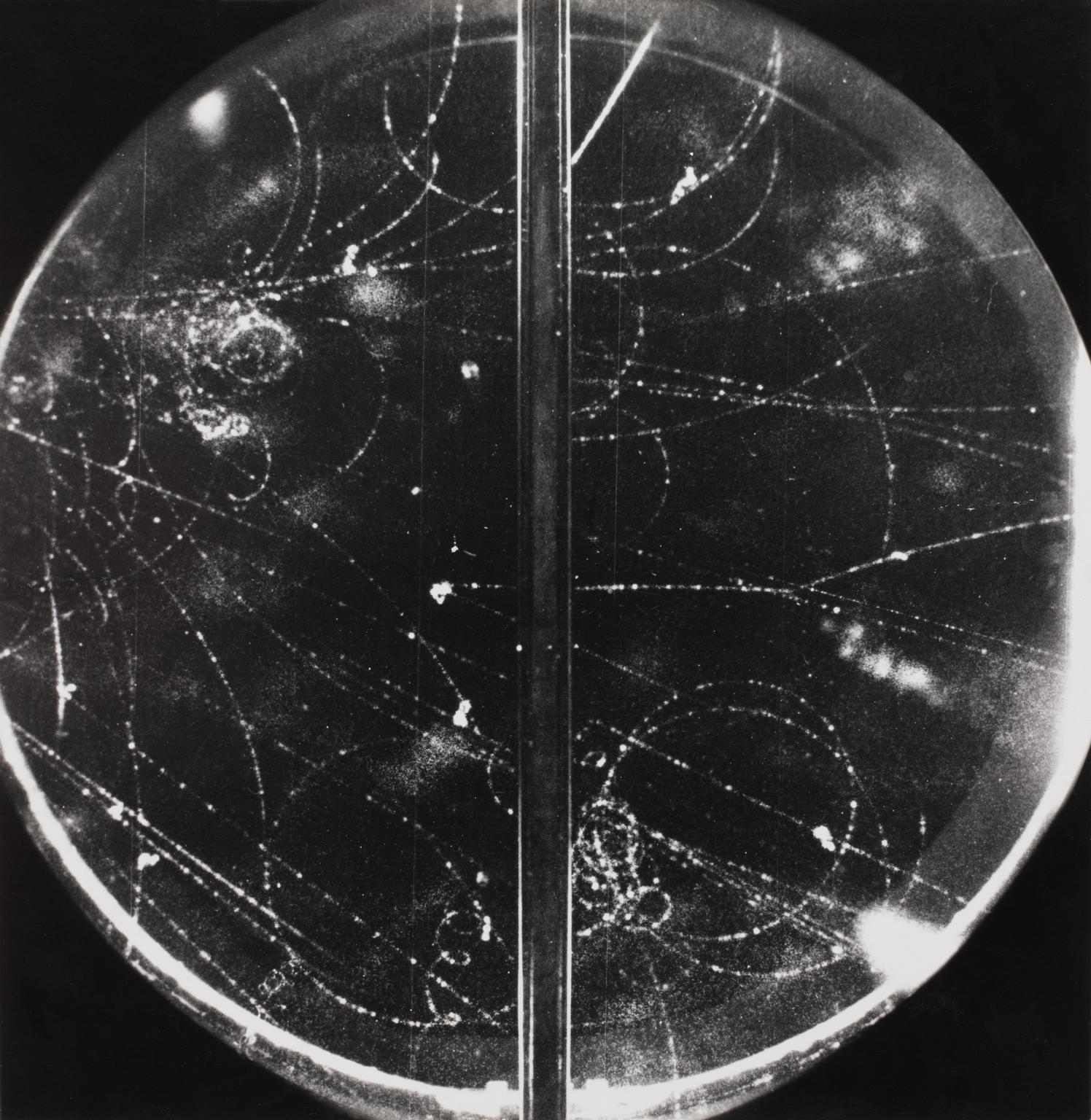
Principle and simulation
The operating principle is to immerse a radioactive sample (which emits high-energy charged particles such as alpha and beta radiation) in a supersaturated alcohol vapor. In this unstable atmosphere, the passage of an energetic particle triggers condensation of the vapor along its trajectory.
Analogy: Similar to how condensation trails appear behind high-altitude airplanes.
The main difficulty is to keep this supersaturated atmosphere stable over time. To do this, we create a strong temperature gradient in a closed chamber: the bottom surface is cooled to around −30 °C, and alcohol evaporates from the top surface. At equilibrium, a thin slice of the volume becomes supersaturated (it just waits for any disturbance to condense). This is where detection happens.
In this slice, the trajectories become visible and the magic happens. You just need a radioactive sample (like Ouraline, a uranium glass) or another particle source (cosmic rays,...).


Here is what the sensitive layer looks like from above. Pick a source, turn on the magnetic field and hover over a track to read the energy and the radius of curvature of the particle that made it.
about this source ▸
green uranium glass (U₃O₈, up to a few %). Natural uranium: U-238 → Th-234 → Pa-234m → U-234. The glass swallows most α, so what escapes is mostly the hard β⁻ of Pa-234m (2.27 MeV), plus a few α from the surface. Almost no γ (a few % at 63–92 keV, under 1% at 1 MeV): expect very few interactions.
Three kinds of tracks show up:
- Alpha (He nuclei, 4 to 9 MeV): thick, bright and straight, about 4 cm long, then they stop abruptly. They are heavy (7300 times an electron), so even a strong magnet does not bend them.
- Beta (electrons, and positrons): thin and wiggly. They are light, so they scatter on every molecule, and they curl in a magnetic field, in opposite directions for e⁻ and e⁺.
- Gamma: no track at all. What you see is what it does when it hits something: a Compton kick (an electron flies off, the photon continues with less energy), the photoelectric effect at low energy, and above 1.022 MeV it can turn into a pair e⁺e⁻.
My goal
So now we know how this machine works... Doesn’t sound too complicated for a cutting-edge 19th-century technology, right?
I could just use dry ice or a modified refrigerator compressor! But my goal is different, and my talent for making easy things complicated took over. I want to build a small, portable, non-mechanical and purely electronic cloud chamber.
My idea is to use Peltier modules to cool the bottom surface, but they are not so easy to use at scale...
Peltier characterization
Who is Peltier? I don't know, but he builds cool stuff. His module is like a tiny refrigerator: when you send a current, it creates a temperature difference between its two faces (thermocouples enter the chat). Unfortunately, thermodynamics is our enemy, and this comes with high power consumption and a massive amount of heat. To build the machine I have to remove this heat (with water cooling), and I have to find the best tradeoff between total heating and temperature difference. To find it, let's experiment !
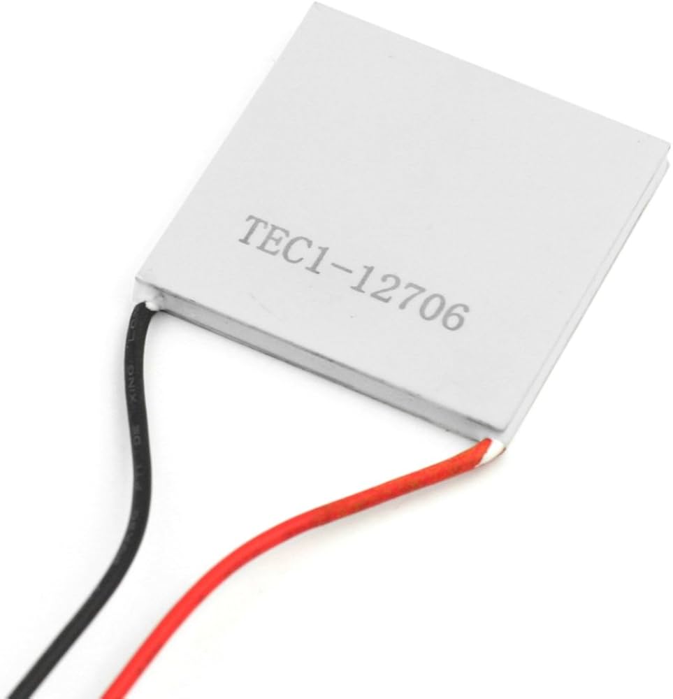
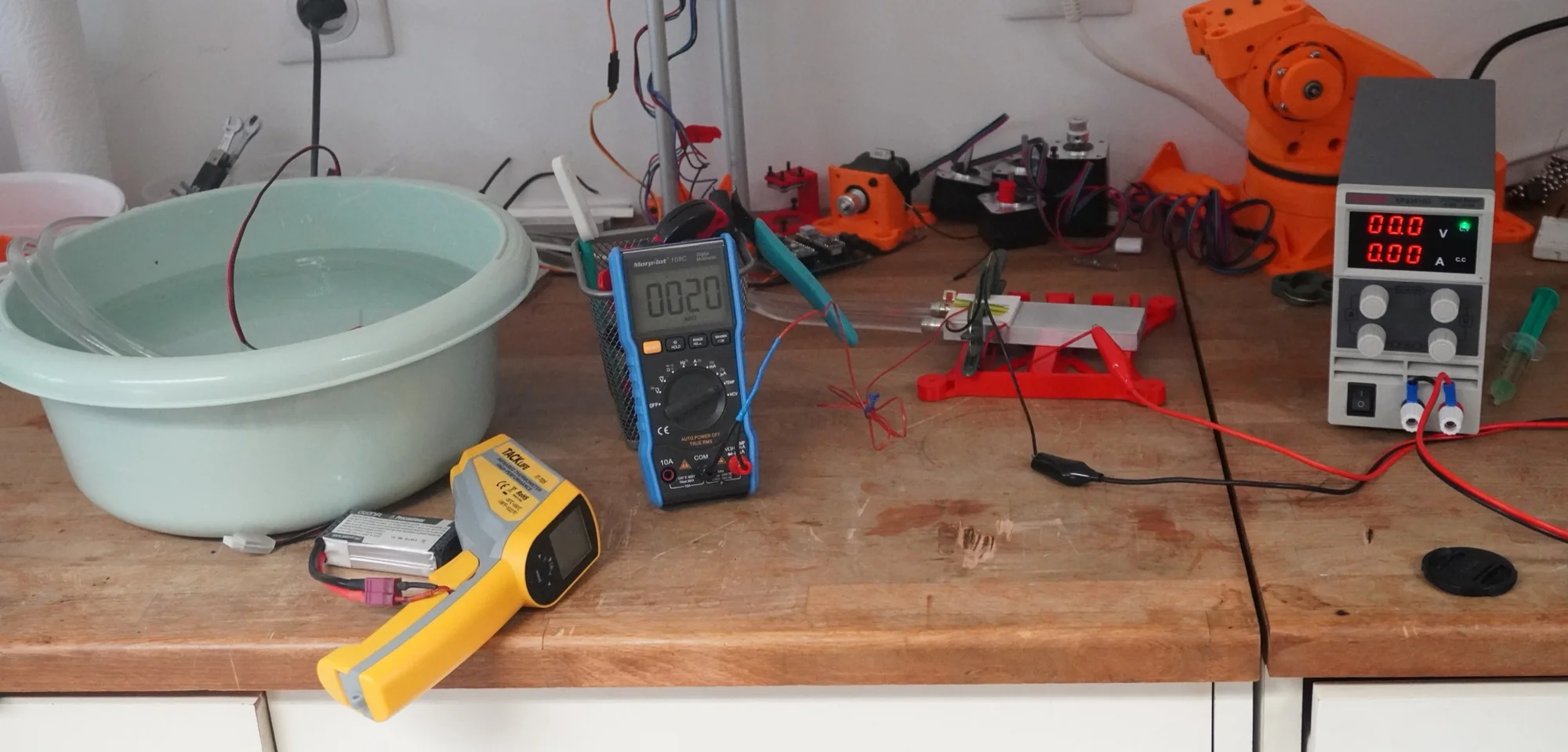
The setup is simple: a TEC1-12706 with its hot face on the water exchanger, a thermocouple taped to the cold face, and an infrared thermometer pointed at the 10 L water tank. No load on the cold face. I increased the voltage step by step, waited for equilibrium, and wrote down the voltage, the current and the two temperatures.
One module
The cold face goes from 20 °C down to −28 °C, and the water stays at 20 °C (the tank is big enough to absorb the heat). The curve flattens quickly: the Joule heat grows like while the cooling does not, so past 11 V I am mostly heating the tank. So 11 V is the operating point for one module.
A Peltier module is also a thermocouple, so the temperature difference creates its own voltage. The voltage needed to drive a current is
where is the resistance of the module and its Seebeck coefficient. Fitting the current gives and mV/K (the line on the right graph).
Two modules in cascade
Now the real thing: I stack two modules, with the bottom one fixed at 11 V and the top one scanned.
The minimum is −36 °C at 5 V on the top module, and everything between 4 and 7 V is almost the same.
The fair comparison is the cooling for the electrical power spent, since every watt ends up in the tank. The cascade at 11 V + 5 V gives K for 57.5 W, against 46.9 K for 46.8 W for one module: 9.9 K colder for 10.7 W more. Worth it, as long as the top module is driven at the right voltage.
- No cold load: with a real load (the copper plate, the glass, the air above) the best voltages will move.
- The current of the bottom module in the cascade (4.25 A) was not measured (my multimeter's shunt resistor exploded :( ), so I borrowed it from the single-module run.
First Prototype
For my first prototype, my goal was to see my first track on a surface of the final size, 12x12 cm. Like a proof of concept.
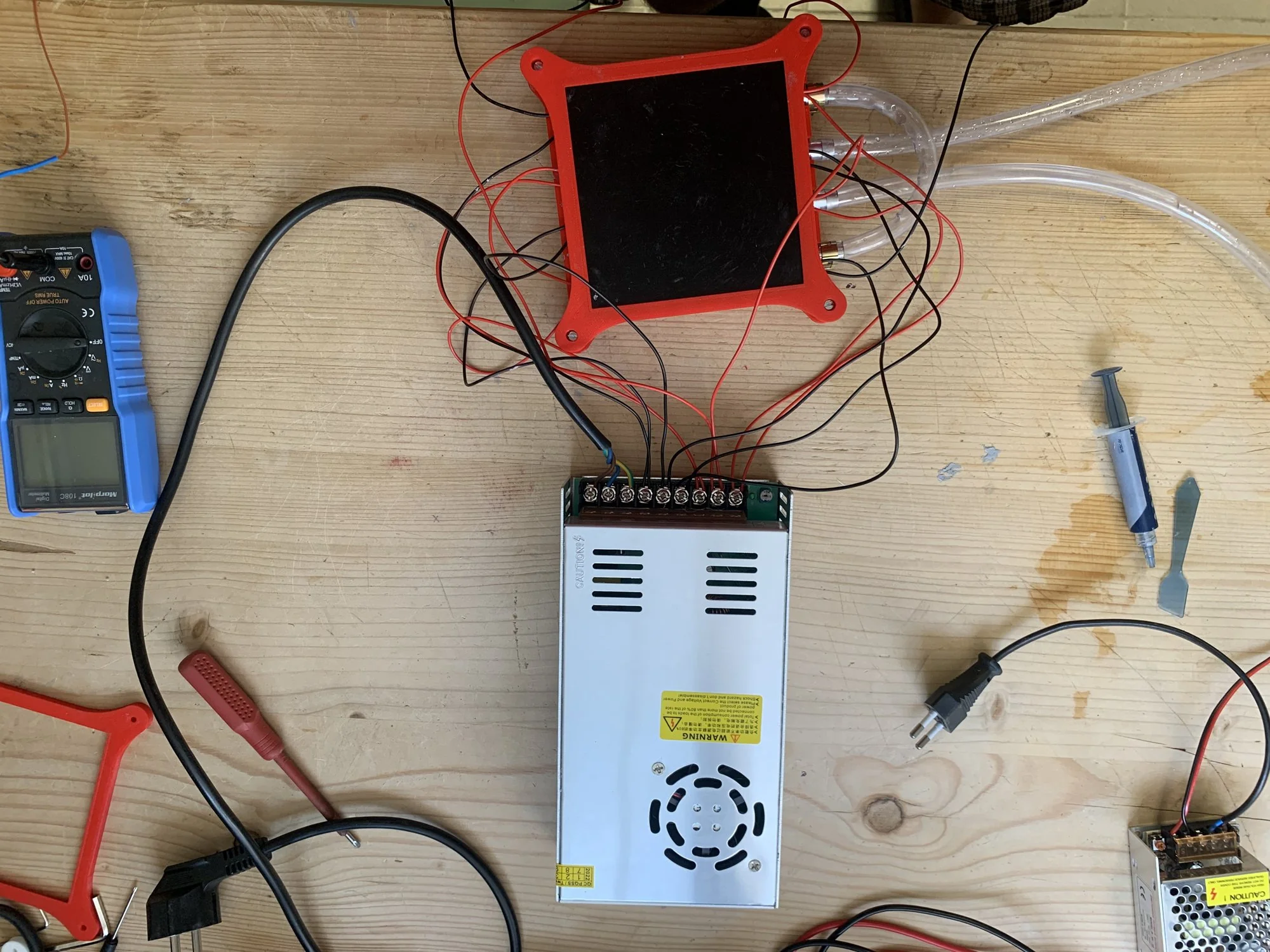
To cover this surface I use 4x2 Peltier modules (4 tiles, 2 layers stacked, like the cascade above). That is at least 230 W of heat to evacuate! Wow, that is hot... ;)
The heat of the bottom layer is then removed by 2 water-cooling radiators, with a small 12 V aquarium pump and car coolant.
Thermal paste is used as glue for all the thermal parts.
On top of the stack, a thin copper plate ♫ painted in black ♫ is the surface where the tracks appear.
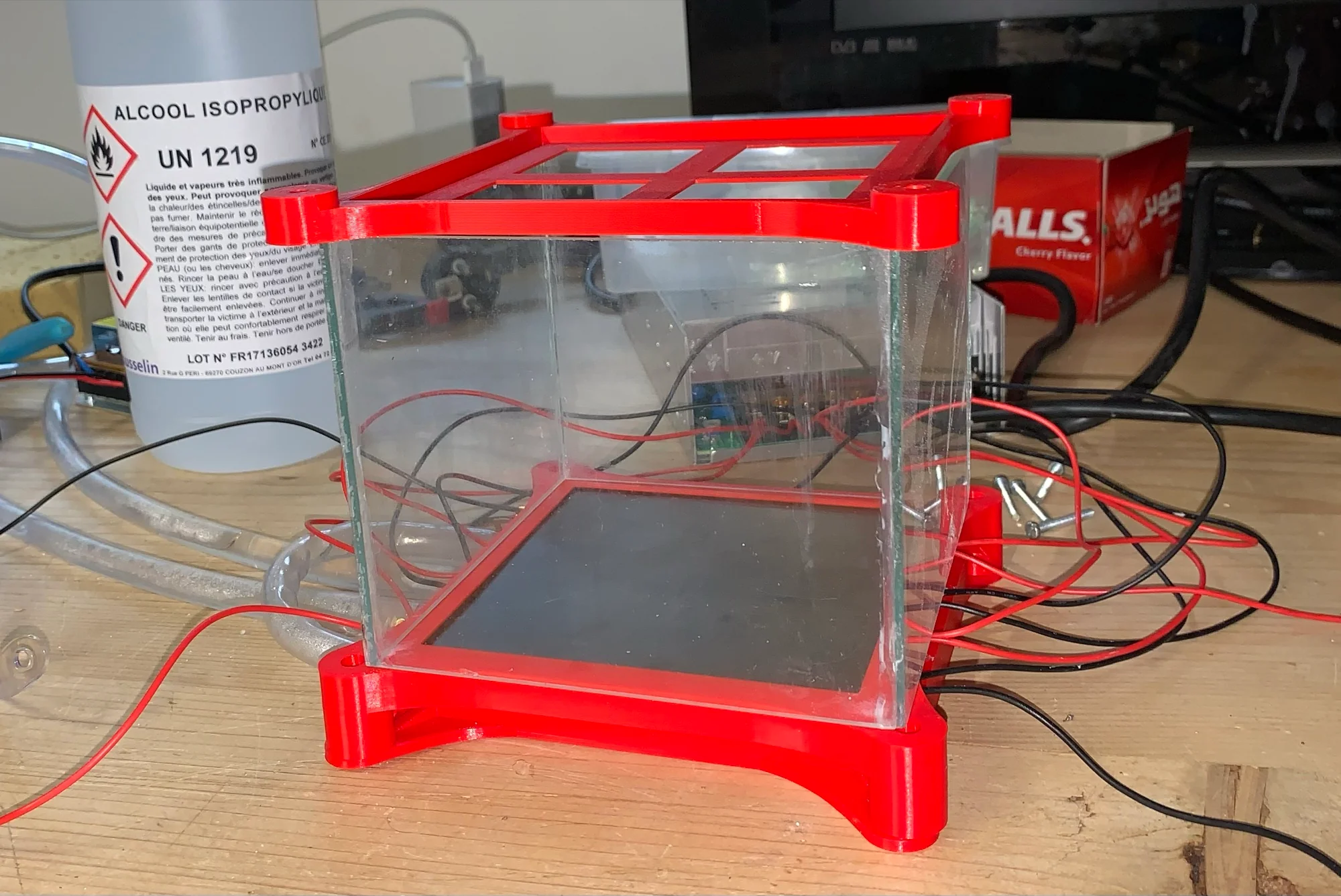
A 3D-printed frame holds everything in place, and a cube of thin glass sheets closes the chamber on top.
Tests
Does it work? Yes. Is it pretty? Not yet.
The plate reaches −20 °C and stays there. It is not the −30 °C I was hoping for, but it is enough to get a thin supersaturated layer above the copper. A red light shines across the plate, and then you wait, staring at a dark rectangle, feeling a bit ridiculous.
And finally, a thin line appears and vanishes in a fraction of a second. Here are two detection events:
They are faint, short-lived and drowned in the fog, but they are real: something crossed the sensitive layer and left a trail of droplets behind it. Which is, unfortunately for my thesis, exactly what the atomic theory predicts...
What went wrong
- Not cold enough. Only −20 °C. The colder the plate, the thicker the supersaturated layer, and the more tracks, so every degree counts.
- The paint. The black paint on the copper plate reacts with the alcohol.
- The light. Lighting the layer well enough to film a track is much harder than expected.
What I will change
- Build a proper high-power supply (PWM + MOSFET) to tune the cascade precisely.
- Add thermal insulation: on a smaller test setup (6x6 cm) it gave me a stable plate at −30 °C!
- Press-fit the thermal components for a better thermal contact.
- Air-cool the water loop (a car or fridge radiator?).
- Monitor the temperature with soldered sensors (plate, water loop, alcohol vapor).
- Make the surface liquid-tight and find a glue that resists alcohol.
- A better alcohol evaporator.
- A mount for a phone or camera, to film.
- A high-voltage source (apparently it helps, but I don't know why).
- A controlled magnetic field, so I can bend tracks like in the simulation above.
Conclusion
I set out to refute particles and, after a lot of alcohol vapor (no joke, be careful, I felt drunk a few times...), I have filmed some of them. I am now forced to consider that my theory may have some flaws... See you soon for another try!